


Controlled porosity in metal 3D printing
Metal powder bed fusion (LPBF, Laser Powder Bed Fusion) offers new possibilities for manufacturing functional intentionally controlled porous structures. In this context, porosity is not a manufacturing defect but a deliberately designed feature that serves a clearly defined technical purpose.
Materflow has conducted an internal research project to investigate the manufacturability of porous structures using the LPBF process. The results show that porosity can be integrated into a component already at the design stage—not as a compromise, but as a feature that enables new applications and improves performance.
Why does porosity matter?
Porous structures have a wide range of industrial applications, including:
- Filtration (for liquids and gases)
- Flow control (e.g. managing pressure differentials)
- Gas diffusers / spargers (e.g. controlling bubble size in liquids)
- Capillary flow and the use of the wicking effect
- Heat transfer (by increasing surface area)
- Damping (noise, vibration, structural oscillation)
- Multi-porosity + solid combinations
Traditional manufacturing methods—such as powder sintering or machining—limit both geometric freedom and the ability to integrate separate components. In contrast, LPBF technology enables the production of single-piece parts that combine solid and porous regions without separate assembly.
Geometric porosity – practical minimum size of pores

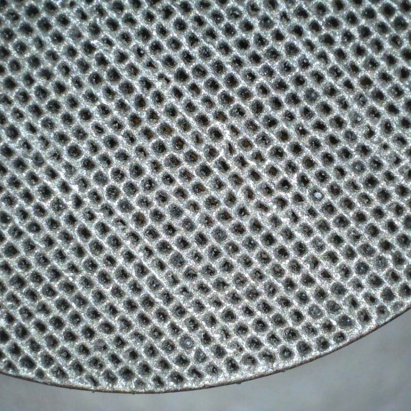
In the first phase of the study, cylindrical holes were tested in a flat test specimen approximately 30 mm in diameter (thickness 3–6 mm). The goal was to determine the lower manufacturing limit by gradually reducing the hole diameter, using the manufacturer’s standard process parameters. The material used was 15-5PH stainless steel. However, the material itself is not a limiting factor, and the same process can be repeated with other commonly used materials such as Inconel 625 or CoCrW.
An additional benefit of 15-5PH steel is its magnetic properties. This allows for the integration of magnetically enhanced separation into the same porous filter structure, for example in applications involving liquids containing magnetic particles.
Results:
- Holes with a diameter of at least 0.20 mm remained open after powder removal.
- 0.10 mm holes were technically manufacturable, but were partially closed and retained trapped powder.
- Bead blasting was not effective—glass beads got stuck in the channels.
- Build orientation had a significant effect: especially downward-facing bottom surfaces were rough and tended to close the channels.
Conclusion: Although 0.10 mm channels can technically be produced, a practical lower limit for geometric porosity is approximately 0.20 mm.
Programmed porosity?
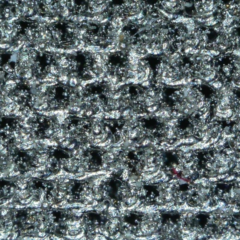
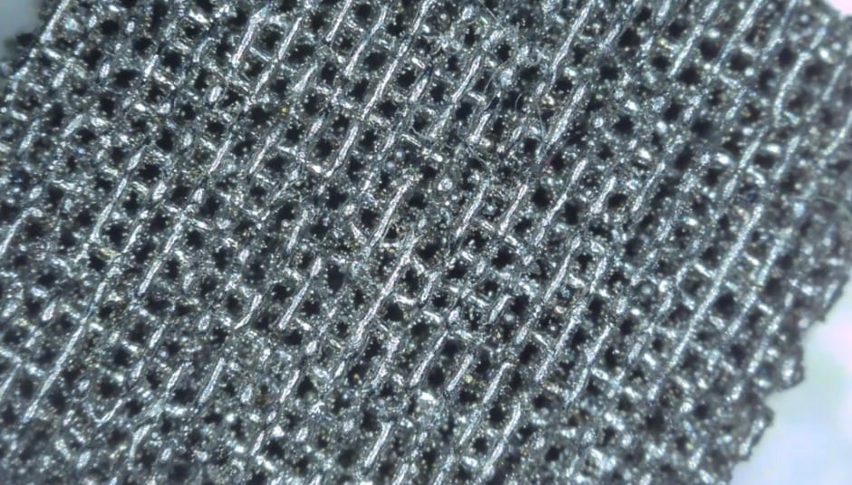
In the second phase of the study, known LPBF process parameters were utilized to induce porosity:
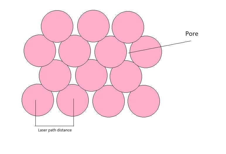
Inter-layer scan strategy: Aligning the scanning direction consistently between layers enables straighter and more continuous channels.
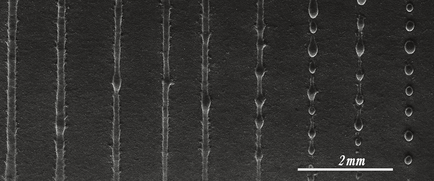
Beading phenomenon (balling): At low laser power and sufficiently high scanning speeds, the melt track breaks up into droplets, forming random voids.
Scan line spacing (hatch distance): This defines the nominal distance and primary orientation of the channels.
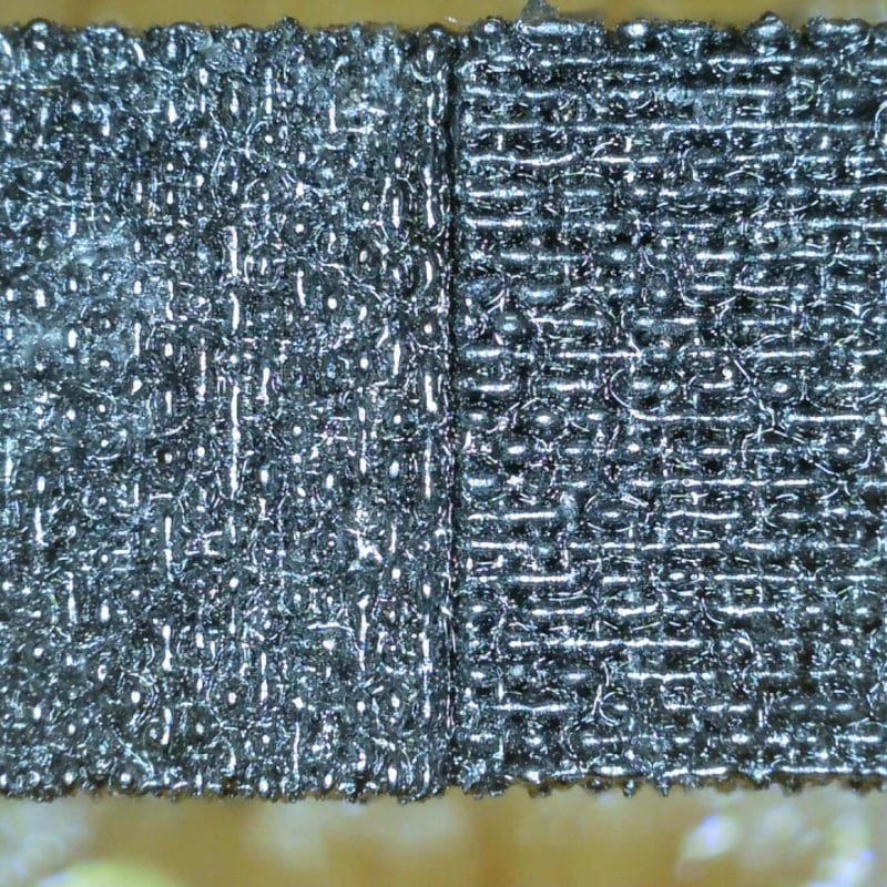
The study involved printing small cubes (5 × 5 × 5 mm) using varying process parameters (including hatch spacing of 0.12–0.20 mm and low laser power, approx. 100 W).

Observations:
- The scan line spacing directly affects the orientation and width of the channels.
- X-ray tomography measured the channel width to be approximately 20–30 micrometres; the actual pore size is likely even smaller.
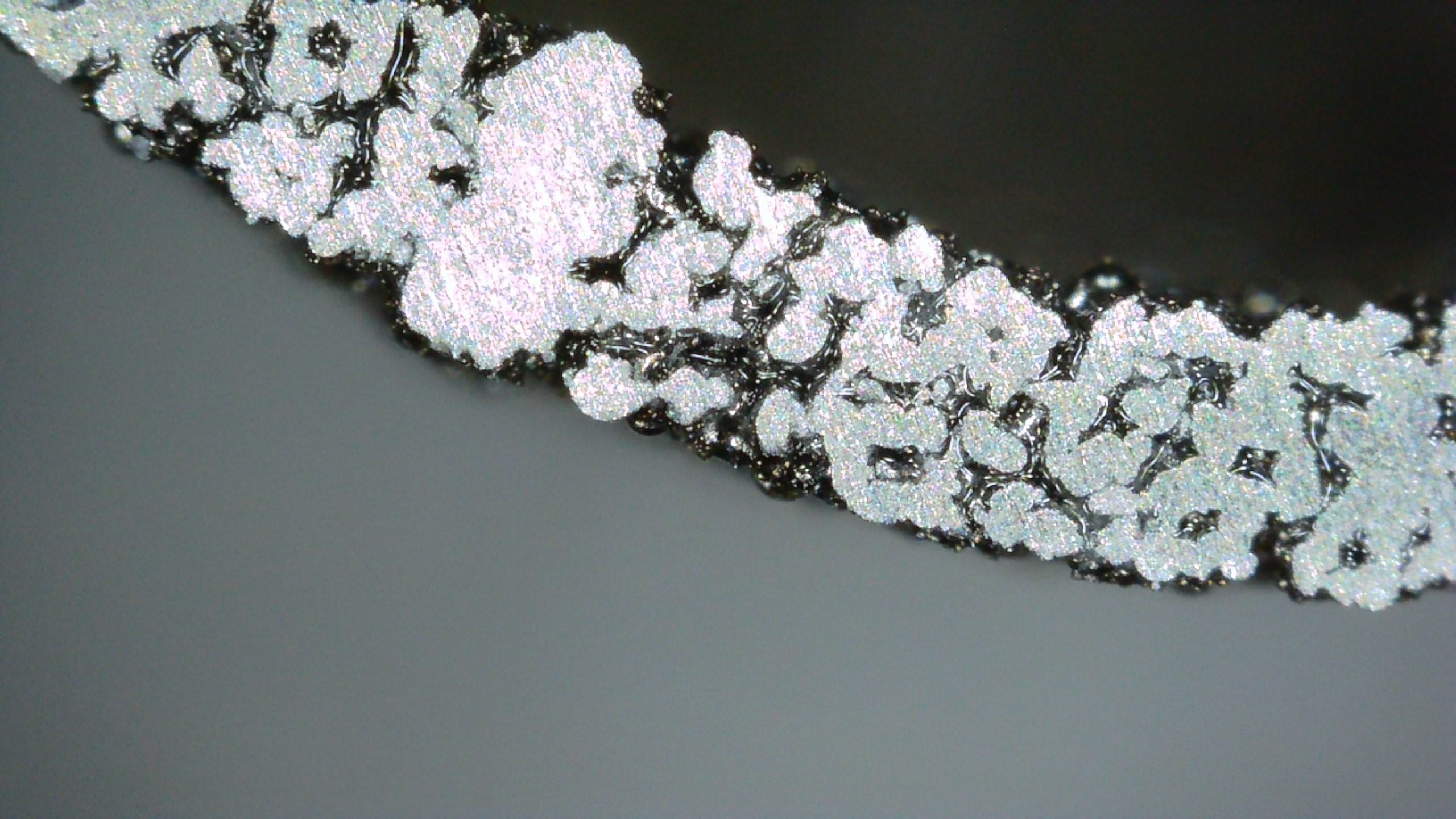
- Some channels contained partially sintered powder, which contributed to the microporous structure and may influence flow characteristics.
- With post-processing methods such as furnace sintering, the trapped powder in the channels can be intentionally bonded into the part as a permanent feature.
Multi-porosity structure – two functions in one
The experiments also successfully produced structures with varying levels of porosity in different regions of the part:
- A denser outer layer acts as a “skin”: it protects and retains impurities while allowing fluid or gas to pass through.
- A more open inner structure forms a flow channel through which fluid or gas can move with minimal pressure drop.
This enables the design of components that combine mechanical protection, filtration, and controlled flow — for example, sensor housings, gas diffusers (spargers), and multi-zone filters.
Challenges and development needs
The fabrication of porous structures brings new technical considerations:
Additionally, verifying pore size, ensuring structural integrity, and assessing long-term durability require further testing.
- The melt track width and powder particle size distribution limit how small the achievable pore size can be.
- The laser spot size defines a practical lower boundary below which functional channels can no longer be reliably formed.
- Residual powder trapped in channels can be a problem (e.g. clogging) — or an intentional part of the structure if sintered in place.
- Post-processing and cleaning methods (e.g. chemical etching, ultrasonic cleaning, fluid flushing, or reverse flow) still require further optimisation.
- Additionally, verifying pore size, ensuring structural integrity, and assessing long-term durability require further testing.
Applications now and in the future
The studied solutions are especially suitable for:
- Multifunctional, single-piece components combining solid and porous sections
- Managing pressure differences and flow control
- Gas and liquid filtration
- Sensor protection
- Capillary structures and thermal transfer applications
- Gas diffusers (spargers) where bubble size control is essential
- Multifunctional, single-piece components combining solid and porous sections
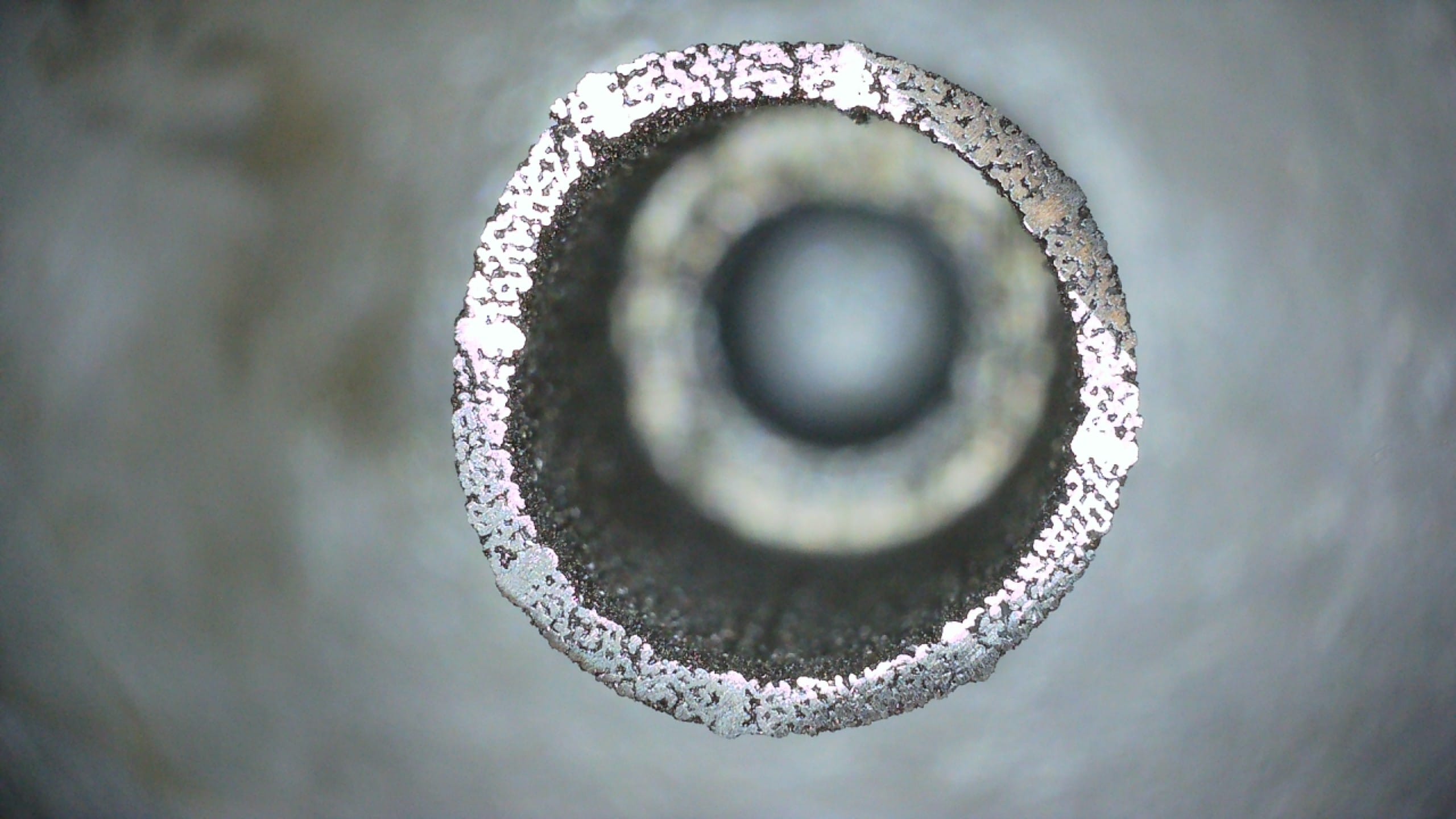
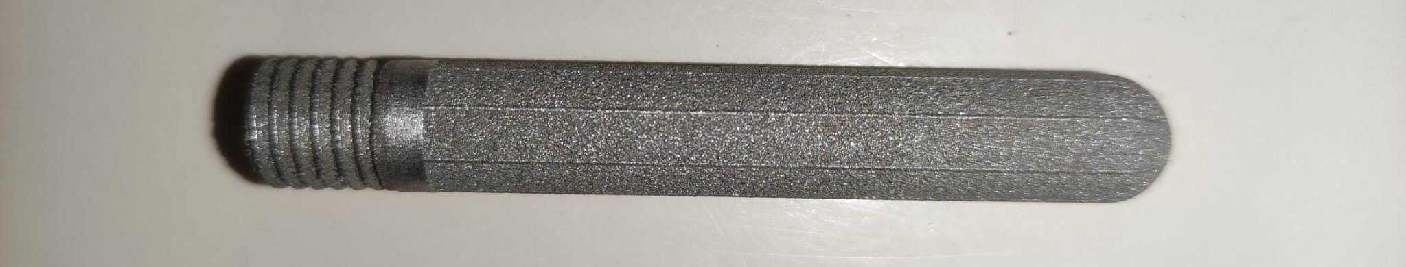
For example, the tested sensor cover consists of a single LPBF-manufactured part that combines a solid threaded section with a porous protective structure. It prevents contaminants from reaching the sensing element while accurately transmitting pressure through microchannels — without the need for assembly, seals, or post-installation steps. The cover can be cleaned, for example, using reverse gas flow or ultrasonic methods.
What’s next?
Materflow is looking for pilot customers interested in applying porous structures in real-world use — whether it’s a filtration solution, a specialised component, or a flow control application.


